Rolive

joined 2 years ago
[–] [email protected] 4 points 6 days ago

I'm in this picture and I don't like it.

[–] [email protected] 20 points 1 week ago* (last edited 1 week ago)

There's also so much bureaucratic pushback to building new houses for all sorts of bullshit reasons. The scarcity is indeed artificial and this is the kind of corruption that we accuse 3d world countries of. Except here it's called "lobbying".

[–] [email protected] 4 points 1 week ago

And fixed immediately after.

[–] [email protected] 5 points 1 week ago

Garry's Mod back when spacebuild still existed. Fun stuff especially all the Stargate add-ons.

[–] [email protected] 2 points 1 week ago

Sounds good. I'm happy with plasma 6.xx on my desktop.

[–] [email protected] 6 points 1 week ago

I don't think I'll be very keen, I've already got one you see.

[–] [email protected] 17 points 2 weeks ago

Hydroponics as well I guess. My DIY automated grow room with a water pump, grow lights, heater and plant shaker (for pollination) always has people think I'm growing weed but I just want chillies and tomatoes.

[–] [email protected] 3 points 2 weeks ago (1 children)

Don't try to paint them purple.

[–] [email protected] 1 points 2 weeks ago

Can't afford to take the chance. Most startups fail and people generally only see the succes cases. If you're not dependent on work you can afford to take chances like this.

[–] [email protected] 2 points 3 weeks ago (1 children)

Regulated? In the Netherlands I can't tell.

[–] [email protected] 25 points 3 weeks ago

"Mycelium schlong"

Linguistic creativity at its best.

[–] [email protected] 31 points 3 weeks ago

Oh for fucking out loud!


Since MOSFETs have a gate capacitance you'd want to limit the inrush of current from the output of a microcontroller to prevent it from getting damaged prematurely. That's what gate resistors are usually good for.

Another thing is that most MOSFETs don't fully activate with a gate voltage below 10V (n type) so usually a microcontroller pin isn't good enough for switching large loads.

I have a 24V system and have made a voltage divider using two 10k resistors to step down 24V to 12V as gate driving voltage which is pulled down with a weaker MOSFET. The power MOSFET essentially ends up with a 10k gate resistor this way meaning it will take a bit longer to fully saturate.

Is too high harmful? In this situation the load is a heater that activates when the room temperature drops below 18C and deactivates when it gets above 22C so fast switching is not an issue.


Does anyone here have experience with this? I'm on the verge of buying the Artme3D extruder kit as it seems to be complete with extruder and spooler. Alternatives like FelFil Evo will sell you the spooler for the same price as the extruder which in my opinion is a scam for something that isn't that complicated.

The next challenge is filament degradation. Ideally you add some virgin plastic pellets to recycled plastic chunks so that there is enough plasticizer still left in there. Could you just add the plasticizer yourself? It commonly is glycerol or PEG which are pretty common and easily attainable chemicals. Does anyone here have experience with mixing additives yourself?


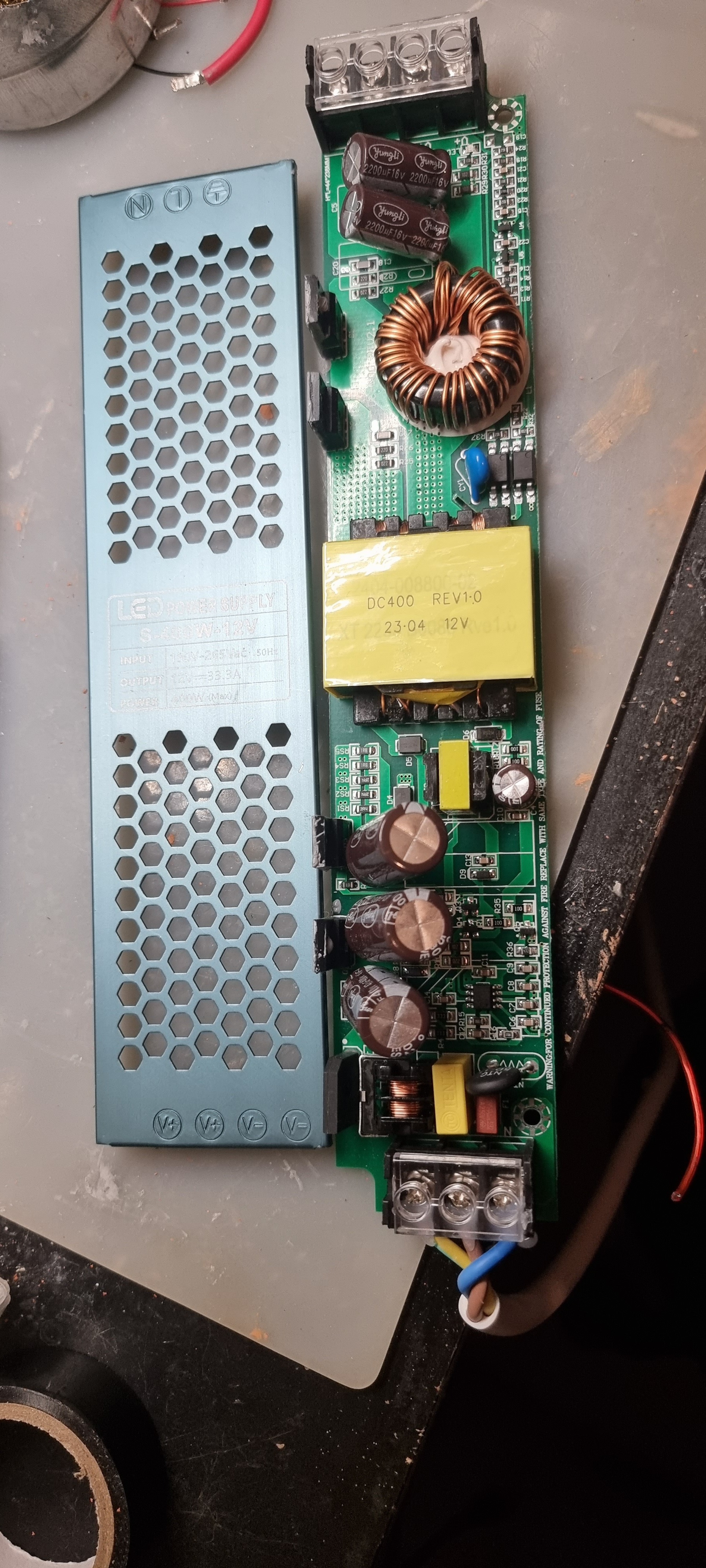
Does anyone recognise these power supplies? They're cheap AliExpress led drivers and I want to change its output voltage to around 22V from 12V. I've read that the way to do this is to adjust the REF voltage on the IC that controls it. It's a KA3845 but I don't understand where that reference voltage is regulated. One voltage is feedback from the output where then other should be a reference.

What would be the best way to approach this? I can't find any schematics on these boards unfortunately.

Thanks.


Does any of you have any experience with this? I'm looking at the Felfil Evo pellet extruder which seems like an acceptable option. One thing I don't understand. Why are the shredder and spooler so ungodly expensive?

I mean, can't you just use an old blender to grind pieces down far enough for the pellet extruder? The finer the better no? Airborne microplastic may be a concern at some point.

Also the spooler. Is that more complicated than a stepper motor that runs at a certain RPM spinning the spool around? With perhaps a mechanism that slows down a bit after X rotations to compensate for the spool getting thicker. Nothing an Arduino can't handle. Also don't grip the spool that tightly so pull strength is more or less equal.

Both the spooler and shredder individually cost more than a pellet extruder does..


This type of battery seems quite easy to DIY. Cheap materials, relatively safe, not flammable.

You can either maken individual cells or make a flow battery which is theoretically infinitely scalable. You'd be limited by the size of the electrode in how much power this battery can deliver.

Has anyone here tried to make a flow battery? And did you have any success with powering something large and energy consuming?

I guess it would also be possible to make a battery out of old buckets, carbon fiber mesh and separator material such as glass fiber.


In a transformer, why are both coils apart from each other? Wouldn't make more sense to have the ferrite core (tube shape), wind the primary coil around that and then wind the secondary coil on top of the primary? So that the magnetic fields are as close to each other as possible?


Hi all

A higher nozzle diameter has the benefit of being able to print faster due to to bigger layer width. There is a tradeoff, you'll have to lower print speed and/or raise temperature to maintain proper layer adhesion. That means that there is an optimal nozzle size for a given print speed/temperature combination. You also don't want temperature too high because it will burn/degrade your filament.

In my experience layer adhesion is quite poor with a nozzle of 0.8mm and it also prevents you from printing finer details (gear teeth for example). The tradeoff versus a 0.4mm nozzle doesn't seem worth it especially if you print overnight.

What are your experiences?


Hi

I'm interested in building my own solar panels mostly for educational purposes. The idea is to use individual solar cells and solder 36 of them in series to get about 18V open circuit voltage. It's what commercial solar panels have as well so its easier to integrate later.

The cells are bonded to the substrate using optically clear silicone or EVA. Not sure which is better. Polyurethane is not good because the mere mention of humidity will cause tons of bubbles.

As for the substrate. Optically clear tempered glass is prohibitively expensive unless bought in bulk. Normal glass is significantly cheaper but could that be a safety hazard? I seriously doubt that thermal shocks are strong enough to break glass sheets unless cold rain falls on it.

Has anyone tried plexiglass/acrylic? It's UV resistant but could bend/warp at higher temperatures breaking the cells.

Perhaps using screen protectors for obsolete phones/tablets could work as well. It's really thin and strong but I don't know it holds up in a hailstorm.

Would love to hear from your experiences in DIY solar panels.


I'm interested in learning how to make a proper PCB rather than perf board with wires all over the place.

view more: ‹ prev next ›